TFT LCD Module
| Link-Sun Standard Products Of TFT Type | ||||||
|---|---|---|---|---|---|---|
| Products | Display Mode | Module Size W x H x T(mm) |
Viewing Area W x H(mm) |
Dot Size W x H(mm) |
IC | SPEC |
| LSMT028-1A | 240 x 320 Dots | 50.0 x 98.8 x 2.70 | 43.9 x 58.22 | 0.06 x 0.18 | ILI9341 |  |
| LSMT032-1A | 240 x 320 Dots | 55.0 x 77.7 x 3.5 | 49.8 x 70.2 | 2.96 x 5.56 | ILI9341 | |
| LSMT035-1A | 320 x 240 Dots | 72.1 x 50.4 x 8.0 | 93.0 x 70.0 | 6.07 x 11.4 | HX8238-A | |
| LSMT043-1A | 480 x 272 Dots | 98.23 x 56.34 x 86.0 | 125.6 x 73.8 | 3.07 x 6.56 | OTA5180A | |
| LSMT070-1A | 800 x 480 Dots | 156.6 x 89.0 x 11.0 | 185.0 x 112.12 | 4.84 x 9.66 | |
|
TFT-LCD Introduction:
TFT-LCD stands for thin-film transistor liquid-crystal display.
TFT-LCD was first invented in early 1960's over the years substantial improvements were made on it and by 1991, it was developed for commercial production for notebook computers, thus the TFT-LCD industry was born.
The TFT-LCD Structure:
It uses liquid crystal to control the passage of light. The basic structure of a TFT-LCD panel may be thought of as two glass substrates sandwiching a layer of liquid crystal. The front glass substrate is fitted with a color filter, while the back glass substrate has transistors fabricated on it. When voltage is applied to a transistor, the liquid crystal is bent, allowing light to pass through to form a pixel. A light source is located at the back of the panel and is called a backlight unit. The front glass substrate is fitted with a color filter, which gives each pixel its own color. The combination of these pixels in different colors forms the image on the panel.
TFT Pixel Element
No matter how the design of the TFT panel changes or the process modified it's structure have to contain TFT devices and LC control region ( ITO film for transmissive type of LCD, metal such as AI is used for reflective type of LCD).
TFT device is a switching device, which functions to turn each individual pixel on or off hence controlling the number of electrons flow into the ITO zone. As the number of electrons reaches the expected value, TFT turns off and these electrons can be kept within the ITO zone.
The above diagram shows the flow of electricity for a TFT substrate, during time t1 to tn gate line driver IC continuously choose to open G1 and allows each source line to charge the TFT pixel which lies along G1 starting from D1, D2 to Dn. Once completed the Gate line driver then choose to open G2 and the process is repeated.
LCD Lighting Theory
Liquid crystal lying between TFT substrates and LCD substrates, will rotates into different angles according to the charges applied to each pixel. When millions of pixels are charged differently, we could obtain millions of LC angles within the area.
Why we need to control the LC's standing angle lies within millions of pixels?
Because we need to use LC's optic rotation nature to control the amount of light passing through the LCD panel. As shown at the following diagram, light from the back light module travels from the TFT panel through ITO electrode, turned by Liquid Crystal and reaches the LCD panel on the top.
A few things can be discovered from the above diagram:
LC angles controls the amount of light being rotated. From the above example: the higher the standing angle the less the light passes through the top substrate.
Light not rotated by LC will be absorbed by the top polarizer. In the Natural world, light travels in random directions; the function of polarizer is to filter most of them and allows only certain light with desired direction to pass through.

6.0" TFT Panel
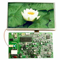
7.0" TFT Panel
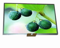
10.2" TFT Panel
3.5" TFT Driver Board
CCFL Convertor
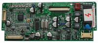
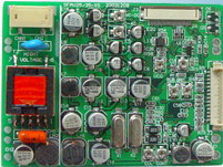
5.0"TFT Driver Broad
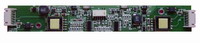
7" Digital Driver Board
7.0"TFT Module